Results 1 to 30 of 30

Thread: Small Scale CHP Steam Engine Project

  1. #1

    Small Scale CHP Steam Engine Project

    NOTE: I had to abandon this project shortly after it began in late 2019 due to unforeseen circumstances. After several years, I was able to start again during early 2023. See Post #21.

    I started a long term project late last year to design and build a small scale combined heat and power steam engine system fueled primarily by wood (and other biomass fuels). I've been derelict on the project for several months now, and I am just getting back into it. So, I figured I would start a thread to document any worthwhile progress. Please note this is a LONG TERM project that will advance SLOWLY due to limited resources (including both time and money). I do not expect to actually have a test engine operating until some time in 2022 - if at all.

    PURPOSE: To create a system that provides the same amount of heat from the same amount of wood fuel as compared to any highly efficient wood furnace, but ALSO provides all electricity demanded by the home during its operation. Design goals include (1) the use of wood fuel with minimal processing(*), (2) highly efficient heat recovery, (3) quiet unattended operation, (4) ease of service and repair by the end user, (5) reasonably compact design that can be transported, (6) efficiency equivalent to providing 1 KWh of DC electricity with no more than 5 pounds of air dry wood.

    PIC OF TEST FURNACE OPERATING:


    (*)I tested the furnace with small wood chunks (about 1" across), large wood chunks (about 3" across), small wood splits, and scrap lumber including 3 foot lengths of 2x4's dropped into the fire tube. It can't seem to tell the difference - but wood must be dry!

    The furnace is the foundation for the entire system, and therefore critical. This crude test unit worked surprisingly well. There was no detectable smoke from the combustion chamber by sight or smell. I could place my face a few feet above the top of the combustion chamber with eyes wide open with no tearing of the eyes and no odor. I estimate the heat output at approximately 15 KW and with peak temperatures approaching 2000F. The basic design of the furnace is sort of a hybrid downdraft FEMA gasifier and rocket furnace. Using a gasifier allows for producing the fuel gas separate from combustion air. In turn, this makes possible greater control of combustion for higher combustion temperatures, a cleaner burn, and a wider turndown ratio - which I verified by operating the furnace for a long period at about 1/4 output (i.e. it still burned hot and clean at the lower output).

    The crude furnace seen in the pic is scrapped. I am building a new furnace fundamentally identical, but with differences that include (1) it mounts on a heavy steel shelf that will accommodate the rest of the system, (2) a high quality 24vdc blower fan mounts under the shelf, (3) the combustion chamber is contained inside a insulated steel drum, (4) the furnace fire tube and the combustion chamber are made of a stainless steel alloy, (5) the drums I am using have lever locking lids for a positive seal, (6) the fuel gas and air are directed into the combustion chamber through a slightly different path.

    Anyway, that's all there is for now. I don't expect another installment (if any) for several months.
    Last edited by buenijo; 10-08-2023 at 09:50 AM.
    "There are no solutions. There are only trade-offs." Thomas Sowell


  2. Remove this section of ads by registering.
  3. #2
    Interesting.

    The double use for both steam drive (electric generation) and heat sounds efficient, but will it be able to run the alternator efficiently without heating the house? Or is the firebox too big for that?

    Will this be a reciprocal (piston) steam engine? Are you thinking of using steam pressure to create a draw through the firebox instead of using output electricity on the fan?
    Quote Originally Posted by Swordsmyth View Post
    You only want the freedoms that will undermine the nation and lead to the destruction of liberty.

  4. #3
    Quote Originally Posted by acptulsa View Post
    Interesting.

    The double use for both steam drive (electric generation) and heat sounds efficient, but will it be able to run the alternator efficiently without heating the house? Or is the firebox too big for that?

    Will this be a reciprocal (piston) steam engine? Are you thinking of using steam pressure to create a draw through the firebox instead of using output electricity on the fan?
    Hello acptulsa. I have good reason to expect the engine system can convert the lower heating value of wood fuel to DC electricity at an efficiency of 8-10%(*). The design maximum charging rate is 1 KWe. This corresponds to between 5 and 6 pounds of well seasoned wood consumed per KWh of DC electricity. Although, I argue the system makes the most sense where heating applications are the priority.

    Yes, the engine uses a piston expander (high compression uniflow with full steam recompression), and it is fully condensing. A small DC blower fan forces air into the base of the furnace.

    (*) On efficiency, I must resort to gross estimates for now. The 8-10% figure is on the low end. However, a fully optimized system based on my design can show 15% conversion of fuel lower heating value to DC electricity (roughly 3.25 pounds of well seasoned wood consumed per KWh electricity - assuming steady state operation). My minimum target is 5 pounds. I would be very pleased with 4 pounds or less. However, I will not compromise system reliability and longevity for higher efficiency. One goal for a fully developed system is to make highly efficient use of the heat from the system. If this can be done, then high efficiency in generating electricity will be less of a priority.

    ADDENDUM: FYI, the design output of my engine system was upgraded to about 1.5 KWe.
    Last edited by buenijo; 09-03-2023 at 02:29 PM.
    "There are no solutions. There are only trade-offs." Thomas Sowell

  5. #4
    Nice not to waste water. Clearly you don't intend to use steam exhaust to create a flow of exhaust in the flue.

    Of course, your condensers are also a source of radiant heat. Steam radiators work well. Sometimes they work too well.

    Can you create electricity without heating the space? Is it good for power in the summer?
    Last edited by acptulsa; 03-24-2020 at 01:56 PM.
    Quote Originally Posted by Swordsmyth View Post
    You only want the freedoms that will undermine the nation and lead to the destruction of liberty.

  6. #5
    Quote Originally Posted by acptulsa View Post
    Of course, your condensers are also a source of radiant heat. Steam radiators work well. Sometimes they work too well.

    Can you create electricity without heating the space? Is it good for power in the summer?
    The condenser will heat water for hydronic heating (along with providing all water heating needs, of course) using a small DC magnetic drive circulating pump to distribute hot water to thermostatically controlled DC fan coil units. Yes, the unit can be operated without heating the space. It's just a matter of dumping the excess heat outside.

    However, this system makes the most sense where winters are harsh and wood fuel readily available. Again, heating applications is the primary purpose. In that setting, the system could provide the same amount of heat from the same amount of wood fuel as compared to any highly efficient wood furnace, but ALSO provide all electricity demanded by the home during operation.
    Last edited by buenijo; 09-03-2023 at 02:32 PM.
    "There are no solutions. There are only trade-offs." Thomas Sowell

  7. #6
    Well it sounds really interesting!
    Quote Originally Posted by Swordsmyth View Post
    You only want the freedoms that will undermine the nation and lead to the destruction of liberty.

  8. #7
    Quote Originally Posted by acptulsa View Post
    Well it sounds really interesting!
    It is surprisingly simple in design - including the control systems - and very few moving parts. However, the devils are in the details - as you know. The main headaches I anticipate include the water feed pump, steam admission valve, and the oil separator. These are already designed and parts are sourced. However, those pesky devils are waiting around the corners.
    Last edited by buenijo; 04-09-2020 at 09:37 AM.
    "There are no solutions. There are only trade-offs." Thomas Sowell

  9. #8
    I considered another way to describe my system which might help some to understand my interest. I linked the following video in another thread on this forum. The purpose of my system is fundamentally the same as this "Cobber" system. However, my system would be A LOT smaller. Also, my system is simpler as there is no engine speed control. The design power output of my engine is constant up to about 1.5 KWe, but it can be adjusted lower by the operator.

    Last edited by buenijo; 09-28-2023 at 01:47 PM.
    "There are no solutions. There are only trade-offs." Thomas Sowell


  10. Remove this section of ads by registering.
  11. #9

    Project Update

    The new furnace and combustion chamber are mounted on one end of a 2' x 3' heavy steel shelf with the 24vdc blower fan mounted underneath. This shelf will eventually accommodate the rest of the system. Right now the shelf is on leveling mounts, but I will eventually switch to casters before it gets too heavy. I went through a few minor iterations before arriving at the current design that proved surprisingly easy to fabricate and assemble. I could build a second unit quickly - so hopefully it tests well. Incidentally, ease of fabrication and assembly is a major part of my basic design that seeks to minimize costs.
    Last edited by buenijo; 07-28-2020 at 09:02 PM.
    "There are no solutions. There are only trade-offs." Thomas Sowell

  12. #10
    Looking forward to following your progress.

  13. #11

    Discussion of Basic Furnace Design

    I mounted some heavy duty casters on the base and drilled the air supply holes to the fire tube. The only thing that remains before firing the furnace is to install insulation in the combustion chamber. This is relatively easy.

    Some good news is I've been offered a practically unlimited supply of small wood splits including a lot of eucalyptus. For those who don't know, this wood is extremely energy dense at well over 30 million BTU per cord (nearly twice as dense as untreated pine lumber) - and burns really hot! Some advise against burning it in traditional fireplaces due to the high oil content, but it's ideal for a gasification furnace.

    I will try to describe the basic design. Consider the basic Top Lit Up Draft wood gasifier (called a TLUD):


    If you understand how the TLUD works, then you will understand how my furnace works. Roughly 1/3 the air (the primary air) is forced into the fuel mass. All free oxygen in the primary air is consumed in the "flaming pyrolysis" section which produces hot wood smoke with carbon monoxide, tar vapors, and soot - all of which are combustible. The rest of the air is admitted in the annular space between the two vessels which heats the air. This preheated secondary air mixes with the smoke in the "burning gases" section. Pretty simple. My furnace does the same thing. However, it includes a sealed fuel hopper on the base furnace, and it shunts the hot fuel gases and preheated air separately into an attached combustion chamber. Pic of first test furnace operating: https://www.flickr.com/photos/184818...-wkkCBj-ocUDM6.

    There are two main reasons for this configuration - plus a third side benefit:

    (1) Conventional TLUD furnaces have limited fuel capacity. Whereas, the size of the fuel hopper for my system can be arbitrarily increased. The fuel chunks fall down into the fire tube as the fuel is consumed.
    (2) I had to design the combustion chamber to accommodate the steam generator. The simplest way to build it was to attach a combustion chamber to the side of the furnace.
    (3) The hopper can be opened and fuel added without any smoke escaping because the combustion chamber geometry provides a low natural draft when the blower fan is off.

    ADDENDUM: If the furnace performs well, then the next steps will be: (1) shape and install the steam generator, (2) assemble the combustion chamber lid, and (3) assemble the water feed pump. I hope to advance the project to this point by the end of the year and start testing the steam generator under pressure by driving the feed pump with a small DC motor. Engine assembly will begin after I know the system generates steam at the required rate, pressure, temperature, and efficiency.

    NOTE: Any development beyond the basic test engine requires outside funding which I would likely pursue via crowd funding.
    Last edited by buenijo; 08-24-2023 at 11:38 AM.
    "There are no solutions. There are only trade-offs." Thomas Sowell

  14. #12

    Furnace Update with Pic

    Just sharing a pic of the new combustion chamber: https://www.flickr.com/photos/184818...posted-public/

    I can fire the unit now. However, I would like to first make a furnace hopper extension. The fuel capacity is rather low without a hopper.

    I will share results when available. It will be a few weeks.

    ADDENDUM: Just a comment to illustrate one aspect of my design philosophy. You can see the combustion chamber is simple. Indeed, "simple" was precisely my goal! A goal for any engineering project should be to avoid unnecessary complexities. Unfortunately, my shoestring budget makes this a time consuming process. Often an ideal component is simply too expensive. However, there is a fringe benefit. Namely, if the furnace works well, then I can replicate it both cheaply and quickly.
    Last edited by buenijo; 07-14-2020 at 10:04 AM.
    "There are no solutions. There are only trade-offs." Thomas Sowell

  15. #13
    Quote Originally Posted by buenijo View Post
    I mounted some heavy duty casters on the base and drilled the air supply holes to the fire tube. The only thing that remains before firing the furnace is to install insulation in the combustion chamber. This is relatively easy.

    Some good news is I've been offered a practically unlimited supply of small wood splits including a lot of eucalyptus. For those who don't know, this wood is extremely energy dense at well over 30 million BTU per cord (roughly twice as dense as untreated pine lumber) - and burns really hot! Some advise against burning it in traditional fireplaces due to the high oil content, but it's ideal for a gasification furnace.

    I will try to describe the basic design. Consider the basic Top Lit Up Draft wood gasifier (called a TLUD):


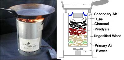
    If you understand how the TLUD works, then you will understand how my furnace works. Roughly half the air (the primary air) is forced into the fuel mass. All free oxygen in the primary air is consumed in the "flaming pyrolysis" section which produces hot wood smoke with carbon monoxide, tar vapors, and soot - all of which are combustible. The rest of the air is admitted in the annular space between the two vessels which heats the air. This preheated secondary air mixes with the smoke in the "burning gases" section. Pretty simple. My furnace does the same thing. However, it includes a sealed fuel hopper on the base furnace, and it shunts the hot fuel gases and preheated air separately into an attached combustion chamber. Pic of first test furnace operating: https://www.flickr.com/photos/184818...-wkkCBj-ocUDM6.

    There are two main reasons for this configuration - plus a third side benefit:

    (1) Conventional TLUD furnaces have limited fuel capacity. Whereas, the size of the fuel hopper for my system can be arbitrarily increased. The fuel chunks fall down into the fire tube as the fuel is consumed.
    (2) I had to design the combustion chamber to accommodate the steam generator. The simplest way to build it was to attach a combustion chamber to the side of the furnace.
    (3) The hopper can be opened and fuel added without any smoke escaping because the combustion chamber geometry provides a low natural draft when the blower fan is off.

    ADDENDUM: If the furnace performs well, then the next steps will be: (1) shape and install the steam generator, (2) assemble the combustion chamber lid, and (3) assemble the water feed pump. I hope to advance the project to this point by the end of the year and start testing the steam generator under pressure by driving the feed pump with a small DC motor. Engine assembly will begin after I know the system generates steam at the required rate, pressure, temperature, and efficiency.

    ADDENDUM: I have also considered the system could power an absorption chiller based on a design I considered years ago. This would be a low priority after space heating, water heating, and water processing systems are developed. I did testing years ago that led me to believe my simple chiller design can work well. This would be the "holy grail" system in my mind: a compact biomass fueled unit that provides ALL off grid energy needs, in accordance with modern standards, and fully serviceable by the end user. No massive battery, no fancy electronics, no solar array required, no massive thermal storage systems, and easy transport if desired. Note the value of a chiller is much higher efficiency as compared to using my system to generate electricity for a convential a/c unit.

    NOTE: Any development beyond the basic test engine requires outside funding which I would likely pursue via crowd funding.
    How does the efficiency of your system compare with a rocket stove?
    9/11 Thermate experiments

    Winston Churchhill on why the U.S. should have stayed OUT of World War I

    "I am so %^&*^ sick of this cult of Ron Paul. The Paulites. What is with these %^&*^ people? Why are there so many of them?" YouTube rant by "TheAmazingAtheist"

    "We as a country have lost faith and confidence in freedom." -- Ron Paul

    "It can be a challenge to follow the pronouncements of President Trump, as he often seems to change his position on any number of items from week to week, or from day to day, or even from minute to minute." -- Ron Paul
    Quote Originally Posted by Brian4Liberty View Post
    The road to hell is paved with good intentions. No need to make it a superhighway.
    Quote Originally Posted by osan View Post
    The only way I see Trump as likely to affect any real change would be through martial law, and that has zero chances of success without strong buy-in by the JCS at the very minimum.

  16. #14
    Quote Originally Posted by jmdrake View Post
    How does the efficiency of your system compare with a rocket stove?
    A gasification furnace is the most efficient way to burn wood. That noted, a properly designed and operated rocket stove is effectively functioning as a gasification furnace. The benefit of a gasification furnace design is superior control over the production of the fuel gas and supply of secondary air. This control makes it possible to show high efficiency over a wider power range and with a wider range of biomass fuel sources.

    First test furnace at full power: https://www.flickr.com/photos/184818...eposted-public
    First test furnace at roughly 1/4 full power: https://www.flickr.com/photos/184818...posted-public/
    Last edited by buenijo; 07-07-2020 at 10:52 AM.
    "There are no solutions. There are only trade-offs." Thomas Sowell

  17. #15

    Discussion of Desiccant Evaporative Cooling

    Just sharing some interesting videos. In previous posts somewhere in another thread I discussed desiccant evaporative cooling as a promising means to provide space cooling using heat from a small steam engine system. An engineer on YouTube made a very good video describing his test unit.


    A follow-up video:


    DISCUSSION: The testing was not under controlled conditions, so I do not consider the results meaningful. There is a lot of room for improvement. A fully optimized desiccant evaporative cooling system could be very impressive. In particular, the approach would be most effective in regions that are both hot and humid as desiccants can take humidy to much lower levels as compared to vapor compression systems. What I like most about this kind of system is the low tech (low voltage DC power can be used, no refrigerants, no special tools for repair). It can be simple and last indefinitely with infrequent low cost maintenance. However, to be practical, it must be effective while significantly reducing electricity consumption relative to vapor compression units.

    People tend to understand humidity plays an important role in cooling. Warmer air holds more water vapor than cooler air. Therefore, warm air at a low relative humidity (meaning relative to how much water vapor can be held at that temperature) can feel more humid than cool air at a higher relative humidity quite simply because it may hold a lot more water! Enter the DEW POINT. This useful concept tells you how low the air temperature must go before the amount of water vapor in the air represents 100% relative humidity. It's a clever way of considering the actual amount of water vapor in the air. For example, at 30F and 100% relative humidity the dew point is obviously 30F. However, at 80F and 60% relative humidity the dew point is 65F and therefore contains a lot more water vapor. Again, it feels a lot more humid as well - because it really is. So, relative humidity is counterintuitive because at different temperatures its comparing apple to oranges so to speak.

    A desiccant system can reduce the humidity more than vapor compression systems such that the dew point is significantly reduced. When this is done, then perspiration become more effective for cooling. Therefore, a desiccant dehumidifier can be effective in a hot and humid climate even without reducing air temperature. Yes, a sufficiently high temperature becomes oppressive. So, at a certain point evaporative cooling might be employed. Interestingly, if the temperature exceeds a certain point, then fans are no longer useful for personal cooling - even under very dry conditions. The reason is rather easy to understand. Sweat evaporates readily under hot and dry conditions to cool the skin. Blowing hot air over a person will only reheat the skin.

    NOTE: With respect to air conditioning in the off grid setting, the superior alternative available today is a ductless unit ("mini split"). These have many qualities that are hard to ignore including the ability to operate over a wide output range (high cooling when an array is producing and low cooling when powered by battery), very high efficiency, a price that is declining in the U.S. market, a long history of use (it is a mature technology), many models come pre-charged with refrigerant which allows installation by the end user, many operate efficiently as heat pumps for space heating, and they have very low starting surge current (so an inverter with a surprisingly low power rating can be used). Operating such a system off grid on a solar array makes a lot of sense. Many models can be dialed down to about 300 watts power consumption while still cooling at a rate greater than 5000 BTU/hour!

    ADDENDUM: The "inverter" compressor drive technology in most mini split systems is now available in window a/c units. The price is MUCH lower!
    https://www.amazon.com/Midea/dp/B08H...s%2C385&sr=8-3
    Last edited by buenijo; 09-28-2023 at 01:56 PM.
    "There are no solutions. There are only trade-offs." Thomas Sowell

  18. #16

    Discussion of Absorption Cooling

    I will fire the furnace this weekend if all goes to plan, and share the results - good or bad.

    I made the previous post primarily for education purposes. It is interesting. To be complete, I'll go ahead and describe another heat powered cooling system that might be configured with a small steam engine system. I did some very limited testing about 7 or 8 years back after acquiring a few pounds of lithium bromide from EBay. I tested the substance based on density and boiling point just to verify it was the stuff I bought, and it passed with flying colors. All I did with respect to testing was learn how to evacuate practically all air from a system by using a combination of cheap refrigerant vacuum pump and steam displacement. Take suction at a low point and start with warm water in the system. As the pressure in the system falls, the warm water boils. Water vapor is less dense than air, and so it rises to the top in the system to displace the air to the suction hose at the bottom. I verified the near complete absence of air by observing the lithium bromide chill the small mass of water down to 32F (after the system was isolated, the lithium bromide solution absorbed the water vapor in the system taking the pressure so low that the small mass of water continued to boil and cool to 32F). The other useful facts I determined is low cost DC mag drive pumps work perfectly under a high vacuum, and 6" schedule 40 PVC pipe holds a high vacuum well. My design is unique for chilling a mass of water DIRECTLY, then circulating the chilled water to a fan coil unit under vacuum. Why not? I mean, the pumps don't care. So, this eliminates a heat exchanger and lowers the chiller water temp - all else equal. The steam engine exhaust condenser would heat the lithium bromide solution that is under vacuum to boil off the water previously absorbed. This very low pressure steam is condensed by the lowest temperature ambient source available meaning air, but a body of water would be ideal. The liquid water from this condenser returns to the chilled water mass in the evaporator.

    The main challenge is achieving a high rate of absorption and evaporation with a low cost and compact design. I have a design worked out, but it's not something I would pursue until after the test engine is completed.

    The following video helps one to understand the absorption chiller. A vacuum pump is used to remove air from a chamber reducing the pressure so low that water boils. The pump continues operating to take the pressure lower and lower by removing water vapor. Since water vapor molecules are more energetic than those in the liquid form (on average), then the liquid water temperature decreases. In this video the water gets so cold it begins to freeze. An absorption chiller does the same thing in a different way by using a desiccant to absorb the water vapor. As long as all non-condensible gases are removed, then water is practically the only substance in the enclosure. So, the pressure can get very low indeed as the desiccant absorbs the water vapor!


    NOTE: Again, this is is all interesting, but powering a small vapor compression a/c unit as an opportunity load on a solar array makes a lot of sense. Optimizing the efficiency of my steam engine system and using it only for heat, backup power, and perhaps water processing and wood drying is the rational alternative.
    Last edited by buenijo; 07-11-2020 at 09:12 AM.
    "There are no solutions. There are only trade-offs." Thomas Sowell


  19. Remove this section of ads by registering.
  20. #17

    Results of Firing New Test Furnace Design with Pics

    I configured the furnace as a TLUD. It took a few minutes to heat up, but once hot it burned clean:

    https://www.flickr.com/photos/184818...posted-public/

    However, the gases would not ignite when directed into the combustion chamber, and a tarry glaze was deposited: https://www.flickr.com/photos/184818...posted-public/

    I am working on the solution.
    Last edited by buenijo; 07-15-2020 at 10:13 PM.
    "There are no solutions. There are only trade-offs." Thomas Sowell

  21. #18

    Discussion of Vapor Compression Chiller Configuration

    Yet another installment describing an unconventional a/c system. The usual disclaimer applies: solar makes a lot of sense for powering conventional small a/c systems. This is just one way a stand-alone system based on my design might be configured.

    It's simple: drive an automotive compressor off the engine via belt drive and use the evaporator to chill a mass of water circulated to the same hydronic fan coil units used for heating. The compressor drive is geared to consume most of the shaft power when engaged. The 24v compressor clutch solenoid (50 watts) is controlled by chilled water temperature feedback.

    The benefits of this configuration over a heat powered unit like those I described previously include: (1) low cost development, (2) compact footprint, and (3) all the high temperature heat from the steam condenser remains available for useful applications. A disadvantage includes increased fuel consumption. However, a fringe benefit is vast amounts of heat from the steam condenser would be available during this time which can rapidly dry wood fuel thereby eliminating the need to store large quantities of wood for seasoning before use.
    Last edited by buenijo; 08-02-2020 at 08:13 AM.
    "There are no solutions. There are only trade-offs." Thomas Sowell

  22. #19

    Update

    I've been brainstorming the problem with the furnace. I now believe the main problem is OPERATOR ERROR. The blower fan pushes too much air, and this is producing a weak fuel gas that is further cooled and diluted with excess secondary air in the combustion chamber. I purposefully selected a new blower fan I knew to be more powerful than required (I figured I would just dial down the output with a controller). However, I did not expect the fan to push so much air as to prevent furnace operation. I got lazy. I should have had the controller on hand.

    I ordered a fan speed controller and purchased plugs for the furnace air supply holes. This will allow control of the air flow rate and the mixture.

    ADDENDUM: Unfortunately, my very limited electronics knowledge got me in trouble. The blower fan is amazing, but both too powerful and apparently too sophisticated. It cannot be controlled with a conventional pwm speed controller, and I am not paying for a fancy unit. Also, the cut in voltage is too high for rheostat control. So, I had to get a new fan. Good news is the new fan is much cheaper. BTW, I got the fancy fan for free. Also, I arrived at an elegant way to install the blower fan to the furnace base that incorporates a damper. This damper will eventually be part of a control system that is critical to operation. The damper was going to be placed elsewhere, but I realized this new location is superior. In fact, it solves several problems. Yeah, I know things are moving slowly - but I expected these kinds of problems. The devils are in the details - and why R&D is so expensive.
    Last edited by buenijo; 07-26-2020 at 12:22 PM.
    "There are no solutions. There are only trade-offs." Thomas Sowell

  23. #20

    Update

    The damper is installed under the base and the new blower fan is contained inside a small steel cap that press fits on the the damper. The purpose of this approach includes: (1) the fan can be easily removed by disconnecting the power supply cord and removing the cap that contains the fan, (2) closing the damper cuts off all air to the furnace while also isolating the fan from any smoke generated from the furnace. It seems to be a good basic design. Assuming the furnace ever tests well, and assuming I ever advance the project to install a steam generator, then the damper will be fitted with an extension spring and solenoid latch configured to shut the damper on high steam generator pressure OR high exhaust temperature (an automatic furnace shutdown feature).

    ADDENDUM: There will be another long delay before any meaningful progress can be made. I attempted another test without success - and identified a couple problems in the process. Unfortunately, I must assemble another furnace. The basic problem is the fuel gas and air flow path I used for the existing unit is throwing off the mixture. Ironically, the original (crude) test unit got it right (the saying "if it's not broke, then don't fix it" come to mind).

    ADDENDUM: Things are rocky (family drama), so the project is on hold for a while. I won't have anything worthwhile to share for some time. I have all hardware required to proceed with a new furnace build (including new steel drums that are slightly larger and heavier than the previous ones), but I cannot resume until this nonsense blows over. Oh well. This is the real world folks.
    Last edited by buenijo; 08-23-2023 at 02:47 PM.
    "There are no solutions. There are only trade-offs." Thomas Sowell

  24. #21
    I restarted the project earlier this year after a bizarre chain of events - and not even accounting for the Covid nonsense. My budget is almost nonexistent. Therefore, it will move like cold molasses. Also, I cannot discuss most specifics on how it is configured. I apologize in advance.

    GENERAL DESCRIPTION: The engine is designed around a small gas engine crankcase mounted to a pump roll cage. A steam cylinder will mount to a plate that seals the top of the crankcase cylinder. The steam piston will connect to the crankcase piston with a rod sealed in a packing gland (crosshead configuration). A permanent magnet alternator will couple directly to the crankshaft PTO for battery charging via an external three phase bridge rectifier. The steam exhaust will be directed to a water-cooled condenser with the heated water used to provide hydronic heating (combined heat and power - CHP). The peak DC battery charge rate is projected to be 1.5 KWe with heat rate at about 5X this value. The steam expander design is a single-acting uniflow with piston-operated steam admission valve and high compression approaching steam generator pressure (roughly 500 psig).

    PROGRESS SO FAR: The crankcase mounts on the pump roll cage. A gearmotor drives the flywheel end of the crankshaft via a freewheel coupling I designed. A sprocket on the gearmotor chain-drives a water feed pump. The gearmotor drives the crankshaft. However, the freewheel coupling prevents the crankshaft from driving the motor. This configuration allows the gearmotor to provide several functions:
    (1) engine starting(*)
    (2) driving the feed pump with precise control of water flow rate
    (3) driving the feed pump in reverse which forces water into the steam generator without rotating the crankshaft - this makes it possible (with a small bypass valve) to generate low pressure steam for heating applications without operating the engine.

    NEXT STEPS: Mount a small oil pump to be chain-driven off the pto shaft (**). Once the oil pump is installed and tested, then I will start assembling the (propane) furnace and steam generator. Only after I can generate steam reliably (and safely) at the required rate, temperature, and pressure will I assemble the rest of the system including steam cylinder, low pressure condenser, and oil separator. Note that a propane furnace is used for ease in development and testing. However, a final design will be wood-fired with a furnace based loosely on designs described in previous posts. I am also interested in a waste oil burner that can also use conventional liquid fuels (see video for a liquid fuel burner demo that shows the basic design I intend to use).

    https://youtu.be/keQ83RTZ1JE?si=E1Fo1i1-zi0xbmO7&t=759

    There is NO timeline as there are too many unknowns, and too few resources.

    (*)My system design calls for stopping and restarting intermittently, even several times each hour, to maintain the charge and temperature of a small battery and small thermal mass, respectively. These will then be drawn upon for electricity and heating demands as required. The system would be operated with battery voltage feedback. If heating demands are high, then a thermostat on the hydronic water would briefly energize a water heating element not to heat the water, but to drop battery voltage briefly to restart the engine and reheat the thermal mass. The idea here is to leverage biomass as an energy storage medium.

    (**)The oil pump is to be mounted differently. See post #28.
    Last edited by buenijo; 10-08-2023 at 09:42 AM.
    "There are no solutions. There are only trade-offs." Thomas Sowell

  25. #22

    AC Generator

    Nothing material to share. Just waiting on parts for oil pump install.

    I will share an interesting configuration that is possible with my engine design. The design uses a three phase permanent magnet alternator (PMA) coupled to the crankshaft and hard-wired to a 24v (or 48v) battery via a rectifier. The engine will operate at a constant speed under this condition. Therefore, it is possible to belt drive a small AC generator head off the engine - provided the PMA is charging.

    To understand what I'm talking about here, imagine the engine is operating with a PMA battery charging rate of 1 KWe. A small AC generator is belt-driven for a speed of roughly 3750 rpm. Now turn on a 10,000 btu a/c unit powered by the AC generator. This draws roughly 850 watts. The AC generator will bog down the engine taking the speed down slightly such that the AC generator is at roughly 3600 rpm for 60 hz. The PMA slows down a little to take the charging rate down to 150 watts. So the DC PMA and the AC generator share the 1 KWe load, and the a/c unit can be cycled on/off so long as the battery is charging.

    I do not suggest this is a good idea, only that it will work. I say go with inverters for AC power and use DC where practical.
    Last edited by buenijo; 08-31-2023 at 02:18 PM.
    "There are no solutions. There are only trade-offs." Thomas Sowell

  26. #23

    Chilled Water System

    Note: I discussed this concept in previous post #18. This post here provides a somewhat more detailed discussion.

    An automotive compressor could be belt-driven off the engine and geared to provide a load slightly less than engine output. When the compressor engages (by energizing the solenoid clutch), then the engine bogs down with most of the engine load transferring from the PMA to the compressor. So battery charging rate goes very low when the compressor is engaged. In this approach, the compressor clutch would engage on low chilled water temperature. The fans on the fan coil units are thermostatically controlled. So, fan speed increases as temperature in the home rises, and vice versa - or the fan speed can be adjusted manually just like a typical automotive a/c system.

    The hardware required for this system is not expensive. Also, it's not terribly complicated mechanically. For example, the compressor would operate at a constant output with more or less constant conditions, and so a needle valve or fixed orifice could be used in lieu of a TXV, and no accumulator is required to store excess refrigerant. It might make sense under the right set of conditions. A side benefit here is, while more fuel is required when using the engine for a/c, there would be A LOT of heat available at the steam condenser that could be used for wood drying.

    ADDENDUM: Automotive a/c systems have high cooling capacity because cars are basically greenhouses on wheels. They also have to be designed for regions like Phoenix, AZ during summer. A typical automotive a/c system in a sedan is capable of a cooling rate on the order of 2 tons. Unfortunately, the efficiency is poor because the heat exchangers are relatively small. For this reason, the temperature differentials must be much higher to achieve the required heat transfer rates. This means the differential pressure across the compressor is much higher than a residential a/c setting. In fact, the compressor can put out a lot more refrigerant than the heat exchangers can handle. Therefore, automotive a/c systems have a high pressure switch that will de-energize the clutch if the compressor discharge pressure exceeds a certain value. However, a typical automotive compressor could support a 5 ton a/c system in a residential a/c setting.

    An automotive compressor used in a residential a/c system would show a pressure differential roughly half that seen in the automotive setting. Therefore, the power required for the same refrigerating capacity would fall by roughly half. Furthermore, the higher evaporator temperature and pressure also implies a higher refrigerating capacity at the same rpm (the density of the refrigerant in the evaporator would nearly double). Therefore, at the same compressor speed, the cooling rate would nearly double. Lower compressor speed and lower differential pressure also implies less wear.

    SOME CONSIDERATIONS: The volumetric efficiency of automotive piston compressors is about 55-65% (with the highest values at lower speeds). The density of R134a saturated vapor at 40F (suitable for a chilled water system) is about 1.05 lb/cf. The latent heat to vaporize a pound of this refrigerant is about 85 btu. I used this information to estimate the required rpm as a function of displacement and refrigeration capacity. A popular Sanden model is 138 cc (about 8.4 ci). My figures show approximately 710 rpm for a one ton refrigeration capacity (it would be about twice this speed in the automotive setting). This changes in direct proportion to the rpm. The required shaft power for this refrigeration capacity under automotive conditions is listed by Sanden as about 2.6 hp. A conservative estimate for the required power with a chilled water system is about half at 1.3 hp. A water-cooled condenser could be driven down to much lower temperatures (and pressures) to take the required shaft power to less than 1 hp.
    Last edited by buenijo; 09-20-2023 at 10:03 PM.
    "There are no solutions. There are only trade-offs." Thomas Sowell

  27. #24
    I did get some parts for the oil pump install. But after tinkering a while, I decided to modify the design. This is an opportunity to explain part of my process here. The design philosophy centers on repurposing readily available low cost parts. It takes a lot of time to source the right parts - and ideas don't always work the first time. This is pretty much how all projects unfold. However, the difference here is I often come across near perfect components that are simply too expensive. I decline not (primarily) because I lack the means, but because the goal is to finally devise a system that can be produced cost-effectively at modest scale. Therefore, parts that are not easy to come by or otherwise costly do not pass muster. Other times, the parts are low cost, but the required modifications are too onerous (i.e. labor costs too high). It's frustrating, but it's the only way I see this working in the long run.

    While tinkering with the oil pump, I did a series of tests on the water feed pump. I operated the gearmotor at a fixed speed that fell within the engine design specs. I then made a series of five test runs each exactly 60 seconds and carefully measured the volume of water using a graduated cylinder. The volume came to precisely 165 ml on each test. The ability to maintain a constant water flow rate into the steam generator is important. Although, I designed a control system (simple and low cost) to compensate for variation.

    I also did a cursory test with a partial vacuum on the pump suction. This reduced and otherwise varied the flow rate (as expected). The implication is the condenser pressure must be maintained above a certain value - and this is not a problem because the system is designed as a CHP unit meaning a higher condenser temperature (and pressure) is inherent in the design. That noted, it's also possible to place a small booster pump.
    Last edited by buenijo; 09-17-2023 at 08:36 PM.
    "There are no solutions. There are only trade-offs." Thomas Sowell


  28. Remove this section of ads by registering.
  29. #25
    Minor progress (I'll take what I can get). I found a low cost oil shaft seal for the oil pump shaft extension I installed. It seems to work well. Also, the damned barbed fittings I installed leak at the threads (chinese seem to have trouble with npt threads - among other things). I couldn't find crush washers of the right size, so I sealed the threads with jb weld. I'm quite certain this will work. The oil pump seems to have a higher flow rate than I expected. I may have to reduce the speed with a larger sprocket. Not a big deal. Looks like it's gonna work. I'll provide a pic after install. Gonna be a few weeks.

    (*)The oil pump is to be mounted differently. See post #28.
    Last edited by buenijo; 10-02-2023 at 09:12 AM.
    "There are no solutions. There are only trade-offs." Thomas Sowell

  30. #26
    Free fuel. Chips. Mulch. Even logs.


    "ChipDrop matches people who want free wood chip mulch with arborists and tree companies who are trying to get rid of it.

    By signing up and placing a request you'll be added to a list of people in your neighborhood who are trying to get free wood chips.

    The next time a local tree trimming company is in your area, they might deliver a load to you."
    Last edited by buenijo; 09-16-2023 at 07:32 PM.
    "There are no solutions. There are only trade-offs." Thomas Sowell

  31. #27

    Steam Generator Test Unit Discussion

    Just sharing thoughts on the upcoming furnace install - just brainstorming really. I expect the furnace/steam generator/condenser test unit to be the single most time-consuming part of the project - partly for the inherent difficulty, and partly because I need to build an outside test stand.

    As mentioned previously, the furnace is based on a propane burner. I selected a low cost 50,000 btu unit available on Amazon. The burner will mount on the roll cage inside a duct flange on which the combustion chamber fits. Additional air admission ports will be provided in the base. For safety, the propane will be supplied with both a regulator and a normally closed solenoid valve. The solenoid is powered with a thermostat that senses steam line temperature. So, if the steam temperature gets too high, then the propane furnace shuts down. Ignition will be achieved using the crankcase ignition system. I already extended the length of the spark plug wire and tested it. Works fine. Once everything is set up properly, then the system will be started by opening the main propane valve and closing a switch. This will energize the starter/feed pump motor (which will fire the spark plug and pump water), and open the solenoid propane valve. Burner output will be more or less constant. Steam temperature will be adjusted by changing the feed pump motor speed.

    For testing, the high pressure superheated steam is to be directed into a stainless steel tubing coil contained in a water bath. A water circulation pump will continuously flow water from a nearby storage tank. This will condense the steam at full steam generator pressure. The cooled high pressure condensate leaves the coil through a needle valve which serves to set the system pressure as indicated by a water pressure gauge.
    Last edited by buenijo; 10-02-2023 at 08:50 AM.
    "There are no solutions. There are only trade-offs." Thomas Sowell

  32. #28

    New Way to Install the Oil Pump

    The oil pump works, but I arrived at a much better way to install it. I had removed the engine camshaft because I simply do not need it. However, I considered that I can use it to drive the oil pump directly. This will eliminate two sprockets, a chain, and the angle bracket - along with a need for a chain guard and chain lubrication.

    Eventually, an adapter plate will mount on the crankcase cover for mounting the alternator. I can then mount the oil pump on this adapter plate and couple the shaft to the M6 threaded rod extension on the camshaft (see pic).


    BTW, this is the oil pump that will mount to the alternator adapter plate. They are designed to install inside the crankcase of small scooter engines. I can buy these for about $5 each. This is a good illustration of my design philosophy. Repurpose readily available low cost parts with minimal fabrication, and minimize the parts count. For example, eliminating the chain drive was significant. I have the (general) design worked out. However, the devils are in the details.

    Last edited by buenijo; 10-08-2023 at 09:44 AM.
    "There are no solutions. There are only trade-offs." Thomas Sowell

  33. #29

    Next Steps

    I put the oil pump in storage. I won't be dealing with that again until the alternator is ready for installation as the oil pump will mount on the alternator adapter plate - and this will not take place any time soon.

    Next step is to start making fire. I need to acquire the propane burner and start assembling a suitable combustion chamber.


    The goal is to establish a high temperature clean burn at a controlled rate of 10-15 KW. Once this is achieved, then a solenoid valve will be installed in the propane line and a spark plug for ignition (using the crankcase ignition system). Hopefully, the system will start easily at the desired burn rate with the flip of a switch. The solenoid valve will eventually be powered off a thermostat that senses steam line temperature (thermostat already sourced). If the temperature exceeds the setpoint, then the solenoid valve will close.


    After this point, I will form the steam generator coil and start building a test stand. I'll start assembling the steam expander only after I can safely and reliably generate steam at the required rate, temperature, and pressure. There is no timeline, but I hope to reach this point by the end of next year.

    NOTE: Incidentally, the steam generator design that uses the propane furnace is designed to accommodate the wood furnace design. The wood gasifier for this system will be functionally identical to the first test furnace I built, but it will be slightly more compact and made of higher quality materials. Parts are sourced.
    Last edited by buenijo; 10-02-2023 at 12:32 PM.
    "There are no solutions. There are only trade-offs." Thomas Sowell

  34. #30

    Air Pump

    Just sharing something I did previously. Earlier this year I built a small air pump that mounted to the small engine cylinder head. It worked perfectly. The idea here was to use the crankcase piston to supply air to the furnace. The air pump assembly was made from ABS plastic sheets that I cut to shape and adhered together with acetone (surprisingly effective). The assembly contained flexible plastic reed valves. The final air pump design could be pulled out from between two cylinder head plates for service and slipped back in easily like a cartridge (the steam cylinder was to mount on the top plate). A single hose on a barbed fitting was connected and air entered through a small filter on the other end opposite where the piston rod gland seal would be. Pop off the filter, then pull out the cartridge. Very cool. Uber simple design. I abandoned the idea in favor of a small dc blower fan because this offers far superior control for easily adjusting the air flow for changing engine output, shutting down, starting up, etc. At the end of the day, it's just too easy to buy a reliable DC blower fan for $20.

    UPDATE: Yet another major delay. I sustained a significant injury (herniated disc) that required surgery. I will be putting the project on hold for a while. Again, there is no timeline - but I hope to have the steam generator assembled and tested by the end of 2024.

    UPDATE (March 2024): I'm recovering very well from surgery, and starting to think about how to proceed with the project. Of course, progress will always be slow as my time and other resources are minimal. Next step is to test the propane burner which is straightforward. Once this is done, then I will form the combustion chamber and the steam generator coil. Again, I hope to be making steam by the end of the year. Once this is completed, then I have good reason to expect the project can move fairly quickly as the steam expander design is more or less completed - and it's surprisingly simple with all parts sourced.
    Last edited by buenijo; 03-20-2024 at 01:31 PM.
    "There are no solutions. There are only trade-offs." Thomas Sowell


Similar Threads

  1. 1903 six HP steam engine powers modern off grid power system
    By Anti Federalist in forum Freedom Living
    Replies: 236
    Last Post: 09-08-2023, 05:22 PM
  2. Replies: 19
    Last Post: 01-17-2011, 01:12 AM
  3. HUGE Ames Iron Works VIM Steam Engine 45HP SIGH:(
    By speciallyblend in forum Freedom Living
    Replies: 2
    Last Post: 01-04-2011, 07:57 AM
  4. Mexico decriminalizes small-scale drug possession
    By disorderlyvision in forum World News & Affairs
    Replies: 14
    Last Post: 08-26-2009, 11:42 PM
  5. a way to test minarchist theory on a small scale
    By heavenlyboy34 in forum Open Discussion
    Replies: 16
    Last Post: 07-04-2009, 08:48 PM

Posting Permissions

  • You may not post new threads
  • You may not post replies
  • You may not post attachments
  • You may not edit your posts
  •